May 06,2026
Apr 29,2026
Apr 22,2026
Apr 15,2026
Apr 01,2026
セルフクリンチングファスナーは、精密に設計されたハードウェアコンポーネント (ナット、スタッド、スタンドオフ、ピン、およびケーブルタイマウント) であり、パンチプレス、アーバープレス、または油圧式挿入ツールを使用して、事前にパンチされた穴に薄い金属シートを押し込むことによって、薄い金属シートに永久的に取り付けられます。熱を必要とする溶接ファスナーや化学結合に依存する接着インサートとは異なり、セルフクリンチングファスナーは、冷間成形プロセスを通じて機械的に固定されます。ファスナーの鋸歯状またはローレット状のクリンチングリングは、圧力が加えられると材料をシートから特別に設計されたアンダーカット溝に移動させ、回転したりパネルから押し戻されたりすることのない恒久的なフラッシュマウントジョイントを作成します。
自己クリンチ取り付けの物理学は、プロセス要件が交渉の余地のない理由を説明するものであるため、理解する価値があります。挿入圧力が加えられると、ファスナーの硬化したクリンチアンビルがパンチ穴に入り、シャンクの形状により柔らかいシート材料が外側に移動し、次に内側に移動してクリンチリングの下のアンダーカット溝に入ります。この移動した金属はアンダーカットの周囲で機械的にロックされ、移動した金属柱のせん断強度によってその押し出し荷重が決まる接合部を形成します。この塑性変形が跳ね返ったり、アンダーカットを埋めることができなかったりすることなくきれいに発生できるように、パネルの材料はファスナーの材料よりも (通常は少なくともロックウェル B 20) 柔らかくする必要があります。
その結果、ファスナーは板金パネルの恒久的な部分となり、一方の面と同一面またはわずかに突出して、標準的な相手ファスナーと併用できる高品質のネジ付きまたはネジなしの接続ポイントを提供します。セルフクリンチング技術は、1940 年代に Penn Engineering (PEM ブランド) によって開発され、特許を取得しました。それ以来、エレクトロニクス、電気通信、自動車、航空宇宙、および産業機器製造における板金アセンブリの世界標準の取り付け方法となり、数十のメーカーが Sherex、Wurth、Optimas、Bollhoff などのブランド名で互換性のある製品ラインを生産しています。
の セルフクリンチングファスナー ファミリは幅広い機能タイプをカバーしており、それぞれがシート メタル アセンブリにおける特定の機械的ニーズを解決するように設計されています。ねじのサイズや材質を指定する前に正しいタイプを選択すると、大幅なやり直し作業が省かれ、取り付けられたファスナーが組み立てられた製品で実際に意図した機能を発揮することが保証されます。
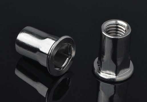
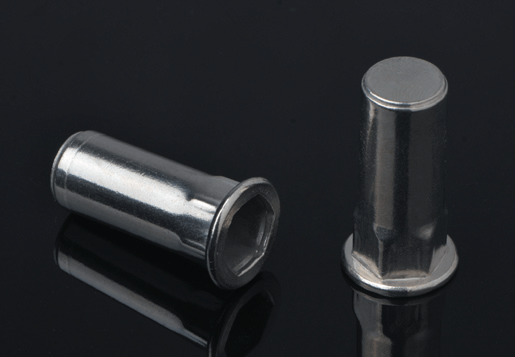
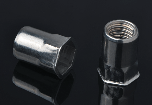
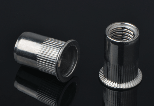
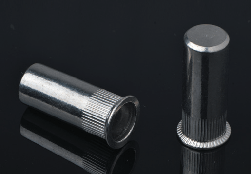
セルフ クリンチ ナット (クリンチ ナットまたは PEM ナットとも呼ばれる) は、最も広く使用されているタイプです。これらは片側からパネルに同一面に取り付けられ、両側から相手ボルトまたは小ネジ用のネジ穴を提供します。取り付けられたナットは、標準のメートルねじおよび統一ねじボルトと完全に互換性のある、きれいな面一またはわずかに盛り上がった表面を示します。クリンチ ナットは、M2 から M12 までの標準ねじピッチ、細目ねじ、およびメートル ISO ねじで利用でき、板金エンクロージャ、ブラケット、構造パネルで使用されるあらゆるファスナー サイズをカバーします。これらは、薄い金属板では信頼性の高いタップねじを形成するのに十分な材料厚さが得られない場合に使用されます。実際には、実質的に 3mm 未満の鋼板や 5mm 未満のアルミニウム板を指します。
セルフクリンチングスタッドは、取り付け面からネジ付きスタッドが突き出ている状態でパネルに永続的に取り付けられ、反対側でナットを受け入れる固定ネジ付きポストを提供します。反対側の面でナットを締めるときにボルトを固定する必要がなく、スタッドはパネルに固定されており回転できないため、組み立てには片側のナットとレンチだけが必要です。クリンチ スタッドは、電子機器エンクロージャへのコンポーネントの取り付け、シャーシ フレームへのパネルの取り付け、および最終組み立て中にパネルの背面にアクセスできない場所で恒久的な雄ねじが必要なあらゆる組み立てに使用されます。全ねじと部分ねじのバリエーションがあり、最も一般的なねじサイズに対応する長さは 4mm ~ 50mm です。
自己クリンチング スタンドオフは、中空のネジ山付きまたはネジ山のない円筒形スペーサーで、パネルに恒久的に取り付けられ、パネルと 2 番目のコンポーネント (通常はプリント基板、カバー プレート、または積み重ねられたシャーシ パネル) との間に明確な固定分離を提供します。これらは、PCB 実装用の電子部品アセンブリに不可欠であり、基板と金属シャーシの間に正確かつ一貫したギャップを維持することで短絡を防止し、冷却のための空気の流れを確保し、組み立て中の PCB のたわみや使用中の振動を防ぐ構造的サポートを提供します。クリンチ スタンドオフは雄 (雄ねじ) 構成と雌 (雌ねじ) 構成の両方で利用でき、アセンブリへのアクセス要件に応じて 2 番目のコンポーネントをナットまたはねじで取り付けることができます。
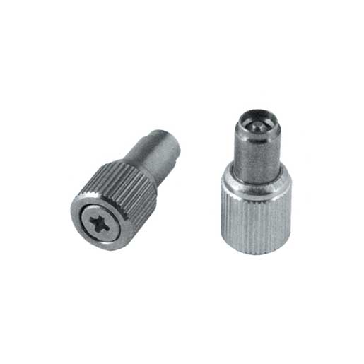
コア ナット、スタッド、スタンドオフ タイプ以外にも、セルフ クリンチング ファミリには、フローティング ナット プレート (組み立て中の穴の位置ずれに対応するために横方向の移動を制限できる)、位置合わせおよびピボット用途向けのロック ピン、パネル面に垂直にコンポーネントを取り付けるための直角ブラケット、きれいな配線配線のためにパネルに永久的に固定されるケーブル タイ マウント、取り外し可能なパネル アプリケーション向けの非脱落型ネジや 4 分の 1 回転ファスナーなどのセルフ クリンチ アクセス ハードウェアが含まれます。各特殊タイプは、基本タイプと同じ基本的な利点を備えた特定の組み立ての課題を解決します。つまり、溶接や接着剤を使用せず、取り付け後の仕上げを必要とせず、薄いシートメタルに片側からのみ永続的に高強度で取り付けられます。
の fundamental requirement for successful self-clinching installation is that the fastener must be significantly harder than the parent sheet material. The clinching action depends entirely on the sheet material flowing plastically into the fastener's undercut groove — if the sheet material is too hard to deform, the installation process crushes or fractures the panel around the hole rather than producing a clean mechanical lock. Most specifications require the fastener to be at least Rockwell B 20 harder than the sheet, which in practice limits compatible sheet materials to mild steel (up to approximately HRB 80), aluminum alloys, and copper-based sheet metals.
硬化鋼、300 シリーズを超えるステンレス鋼シート、またはその他の硬質金属へのセルフクリンチは不可能であるか、定格値と比較して大幅に性能が低下した取り付けが行われます。より硬いシート材料でのファスナーが必要な用途では、代わりに溶接ナット、ブラインド リベット ナット、接着インサートなどの代替技術を使用する必要があります。これは、エンジニアがセルフ クリンチング ファスナーを初めて採用するときに遭遇する最も一般的な仕様エラーの 1 つです。つまり、シートの硬度をファスナーの硬度要件に対して検証せずにステンレス鋼の筐体に適用することです。
| シート素材 | 一般的な硬度 | 適合するファスナーの材質 | セルフクリンチは適していますか? |
|---|---|---|---|
| 軟鋼・低炭素鋼(CR、HR) | HRB 40 ~ 80 | 炭素鋼、ステンレス鋼 | はい — 理想的です |
| アルミニウム合金 (1xxx、3xxx、5xxx、6061) | HRB 25–65 | 炭素鋼、ステンレス鋼, aluminum (special) | はい - 正しいファスナーグレードを使用 |
| 銅・黄銅板 | HRB 30–70 | ステンレス、スチール | はい - 適切な硬度差がある |
| オーステナイト系ステンレス鋼(304、316) | HRB 75–95 | 焼き入れ鋼のみ | 限界 — 硬さを確認します。代替案を検討する |
| 焼入れ・高張力鋼 | HRC25 | 実用的ではない | いいえ - 溶接ナットまたはブラインド リベット ナットを使用します |
アルミニウム シート アセンブリの場合、標準的なスチール製セルフ クリンチング ファスナーは正しく取り付けられ、高い引き抜き荷重を提供します。これは、硬化スチール製ファスナーと軟質アルミニウム合金の硬度差が十分以上であるためです。ガルバニック互換性に関する質問は、取り付けの互換性に関する質問とは別のものです。アルミニウム パネルに取り付けられたスチール クリンチ ナットは確実に保持されますが、湿気の多いまたは湿った使用環境では界面でガルバニック腐食を引き起こす可能性があります。腐食環境のアルミニウム パネルの場合、利用可能な場合はステンレス鋼のセルフ クリンチング ファスナーまたはアルミニウムのセルフクリンチング ファスナーを指定し、アルミニウムの取り付け用に設計されたアルミニウム リブナット専用の製品 (硬度差を維持するためにより柔らかいファスナー本体を使用する) が、指定されたシート合金グレードに使用されていることを確認します。

すべてのセルフクリンチファスナーには、クリンチ動作によって信頼性の高い機械的ロックを生成できない最小シート厚と、性能が最適化される推奨シート厚があります。これらの制限はガイドラインではありません。最小値よりも薄いシートにセルフクリンチング ファスナーを取り付けると、取り付けは完了したように見えますが、引き出しおよび押し出しの耐荷重が大幅に減少し、通常は定格性能の数分の 1 で失敗します。
スチール製セルフクリンチングナットの最小シート厚は、通常、M2 ~ M3 ねじサイズの場合は 0.5 ~ 0.8 mm ですが、M6 ~ M8 サイズの場合は 1.2 ~ 1.6 mm まで増加します。最小厚さは、定格引抜荷重を達成するためにアンダーカット溝に塑性的に流入する必要がある材料の量によって決まります。シートが薄すぎると、アンダーカットを適切に埋めるのに十分な材料がありません。最大シート厚も指定されており、それを超えるとファスナー本体がシートから十分に突き出てクリンチアンビルに正しく係合できなくなります。ブラインド リベット ナットのグリップ範囲のコンセプトは、自己クリンチと同等の概念を持っています。各製品は、定義されたパネル厚さのウィンドウに合わせて設計されており、そのウィンドウ内に留まることがパフォーマンスにとって不可欠です。
セルフクリンチングファスナーには、正確な直径のきれいな丸穴が必要です。取り付け穴の直径は、一般的なドリルの公差よりも公差が厳しく、通常は±0.05 mm 以上に指定されています。生産のセルフクリンチ取り付けでは、パンチ穴の方がドリル穴よりも強く推奨されます。パンチ穴は、パンチとダイのクリアランスが正しく設定されている場合、パンチの入口側 (ファスナーがクリンチする側) にバリがなく、高い生産率で一貫してきれいで正確なサイズの穴を生成できるためです。ドリル穴はプロトタイプや少量の作業に使用できますが、両面のバリ取りと、ファスナーが要求する厳しい公差範囲内に収まるように慎重な直径制御が必要です。レーザーカット穴はますます一般的になり、優れた直径精度が得られますが、切断端にわずかな熱影響ゾーンがあり、穴壁の材料の延性が低下する可能性があります。生産用のセルフクリンチング用途でレーザーカット穴を使用する前に、設置テストで確認してください。
セルフクリンチングファスナーは、ベンチプレス、アーバープレス、Cフレームプレス、またはプロダクションパンチプレスのいずれかで、平らで滑らかな取り付けアンビルを使用して取り付けられ、パネル表面に垂直に締め付け力を加えます。アンビルはファスナーのヘッドに接触し、パネルは平らな支持面上に置かれ、ファスナーのシャンクが下穴から突き出ています。プレスが閉じると、ファスナーがシートに打ち込まれ、クリンチリングが 1 回の滑らかなストロークでシート素材をアンダーカット溝に変形させます。
の installation force required depends on the fastener type, thread size, sheet material, and sheet thickness. Typical installation forces range from approximately 1 kN for small M2 clinch nuts in thin aluminum up to 40–60 kN for large M10–M12 clinch studs in steel sheet. These forces are well within the capacity of standard bench arbor presses for small sizes, but larger sizes require a properly rated C-frame or hydraulic press. The installation must be performed with the anvil and support surface parallel — any angular deviation causes the fastener to install at a tilt, misaligning the thread axis and reducing pull-out strength.
大量の板金製造 (サーバー ラックの製造、自動車の車体部品の製造、電子機器の筐体の製造) では、専用のフィードアンドインサート機械またはパンチ プレス ツールに統合された挿入モジュールを使用して、セルフ クリンチング ファスナーが自動的に取り付けられます。自動挿入機は、ボウル フィーダーまたはテープ アンド リール パッケージを使用して、個々のファスナーを毎分数百個の速度で挿入ヘッドに方向付けして供給します。また、視覚または力監視システムを使用して、ファスナーの誤装着または欠落を検出し、組み立てプロセスに進む前に取り付け欠陥のあるパネルを排除します。一部のパンチプレスメーカーは、穴開け操作と同じプレスストロークでファスナーを取り付けるセルフクリンチ挿入ツールを提供しています。これにより、別個の挿入ステップが完全に不要になり、ファスナー取り付けの追加サイクルタイムがゼロになります。
For flexible production environments handling multiple product types, robotic self-clinching installation systems using collaborative robots (cobots) equipped with insertion end-effectors are growing in adoption.これらのシステムは、専用のハードツールを使用せずにさまざまなファスナー タイプやパネル レイアウトに合わせてプログラムでき、自動化された機器の設置の一貫性と手動操作の柔軟性を提供します。これは、多品種中量の作業を扱う請負板金製造業者にとって魅力的な組み合わせです。
セルフクリンチングファスナーの性能は、使用中に受ける力に対するファスナーの抵抗を定義する 3 つの荷重値によって特徴付けられます。セルフクリンチングファスナーがジョイントの設計に適切であることを検証するには、各値が何を意味し、それがアプリケーションの荷重条件にどのように関連しているかを理解することが不可欠です。
のse rated values are specified by manufacturers at a defined installation force on a specified sheet material and thickness. Installing at lower than the specified installation force — due to an underpowered press or an operator stopping the stroke early — produces installed fasteners with significantly lower actual performance than the published ratings. This is why force monitoring on automated insertion equipment is not a luxury but a quality requirement for any application where the joint loading approaches a meaningful fraction of the published performance values.
セルフクリンチングファスナーは、多くの板金用途において溶接ナットやブラインドリベットナットと競合しますが、正しい選択は、板材、厚さ、生産量、表面仕上げの要件、および組み立てアクセスの制約の特定の組み合わせによって決まります。単一のテクノロジーが普遍的に優れているということはありません。それぞれが特定の状況で優れています。
溶接ナットは最高の接合強度を提供し、シートの硬度の影響を受けませんが、片面または両面から溶接にアクセスする必要があり、薄いパネルを変形させたり、近くのコーティングを損傷したりする可能性のある熱が導入され、溶接後の洗浄や溶接領域の再仕上げが必要になることが多く、適格な溶接作業のコストが追加されます。これらは、接合強度の要件が圧入ファスナーで提供できる強度を超える厚い構造用鋼の用途や、自己クリンチが実現できない材料に最適です。ブラインド リベット ナットは、プレスを使わずに簡単な手動ツールまたは空気圧ツールを使用して片側からのアクセスのみで取り付けることができるため、現場での取り付けや改造の用途により汎用性が高くなりますが、別の設定ツールに依存するため、パネル面から突き出た外部フランジが残り、面一の自己クリンチ取り付けよりもきれいではありません。
セルフクリンチングファスナーは、生産量がプレス工具に見合ったものである場合、パネルの両面の表面仕上げを維持する必要がある場合(溶接スパッタや外部フランジがない場合)、シート材料がクリンチングできるほど十分に柔らかい場合、およびパネルの塗装または組み立て前に取り付けを実行できる場合に最適です。スチールやアルミニウムのシートに同等の定格荷重でリブナットを使用するよりも、よりクリーンで専門的な取り付けが可能です。また、別個の工具係合ネジがないため、マンドレルの損傷を管理する必要がなく、設定ツールによるネジ係合深さの制限もないことを意味します。サーバー シャーシ、電気キャビネット、自動車用ブラケット、医療機器ハウジングなどのシート メタル エンクロージャの大量生産では、量が工具への投資に見合った場合、自動化装置によって取り付けられるセルフ クリンチング ファスナーが通常、ジョイントあたりの総コストを最も低く抑えます。
Ordering self-clinching fasteners without a complete specification is a reliable path to receiving the wrong product — the combination of fastener type, thread size, sheet thickness, and material options available within a single manufacturer's range runs to hundreds of individual part numbers, and catalog descriptions that appear similar can differ in critical dimensional details.完全な仕様には、次のすべてのパラメータが含まれます。
Copyright © Steady Industrial Fasteners Co.、Ltd。 All Rights Reserved


 en
en 
 +(86)-133 8863 9264


")
")
")
